Well, if you can manage a saw and a screwdriver, you can build my low tech, wooden lift adapter. It does exactly the same thing that its metal counterpart does, and it works pretty well. Now, I'm not going to sit on it, like Ross does on his, but this adapter is more stable than simply using your Larin lift by itself because the center of gravity of the motorcycle is more nearly directly over the lift. Works especially well with Interstates, bikes with a heavy ass.
However, my legal disclaimer: What works for me may not work for you, and I accept no responsibility for anything that happens if you decide to build this lift adapter. This page is provided for informational purposes only. There, now the lawyers are happy.
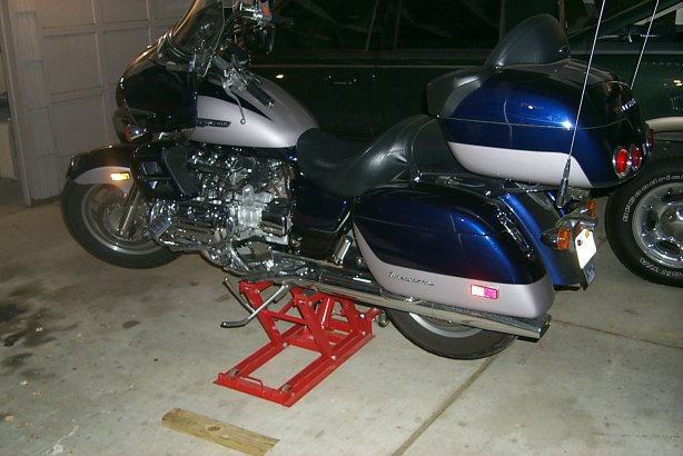
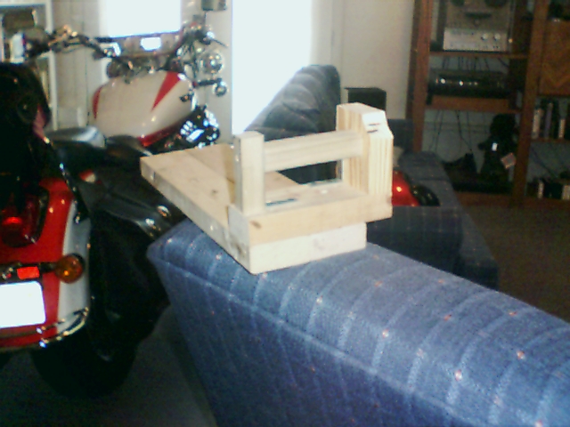
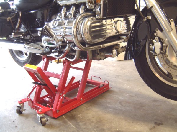
Let's start with a few photos of the bike on the "Low Tech Adapter".
A view of the adapter from the right side of the motorcycle.
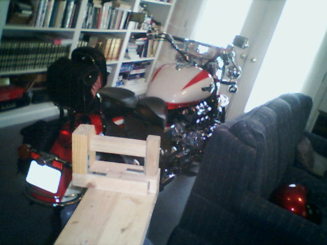
And a peek from the left.
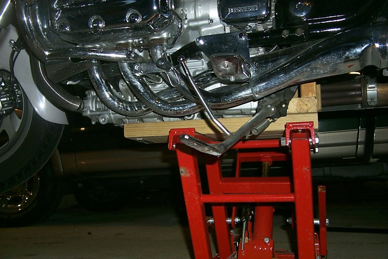
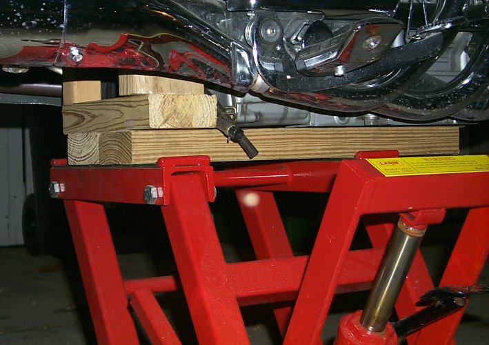
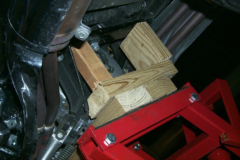
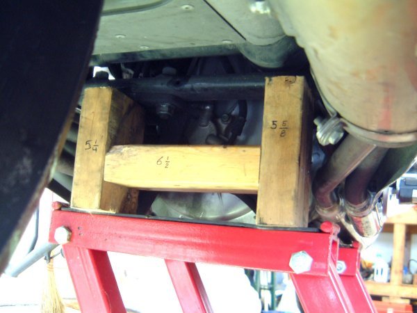
Here is what it looks like under the bike... the contact points for the lift adapter. Depending on how you have your under bike air horns mounted, this adapter may work for you. Two things to note: First, the right side 2 x 4 chunk is about as close to the edge of the crossmember as you can get... you might be able to add 1/2 inch to the width of the adapter... but then positioning it becomes a major PITA. Second, the left side is designed to snuggle into the kick stand mount.
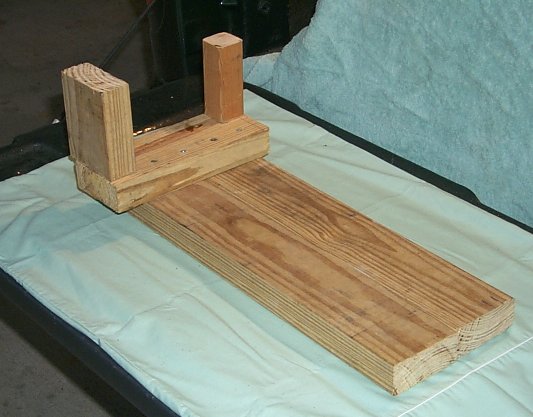
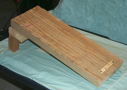
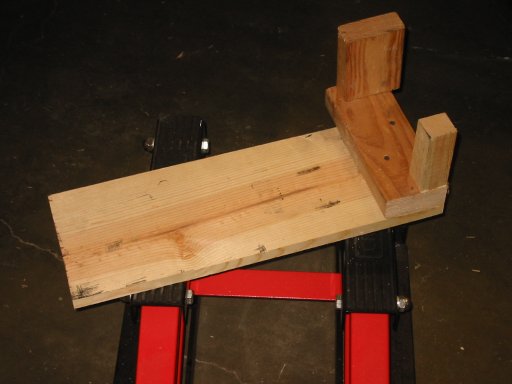
Here are the specs on the adapter itself. The pic below gives you a perspective view of the adapter. The whole thing is made from treated 2" x 4" lumber with one little chunk of 2" x 2". It doesn't have to be treated... that was what I found in my garage. Note that the actual dimensions of finished lumber are not the same as the nominal size. A 2" x 2" piece of lumber is actually 1.5" x 1.5", while a 2" x 4" is actually 1.5" x 3.25". You will also need 10, 3 inch long deck screws, plus a mending plate (more below).
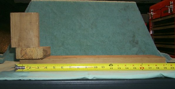
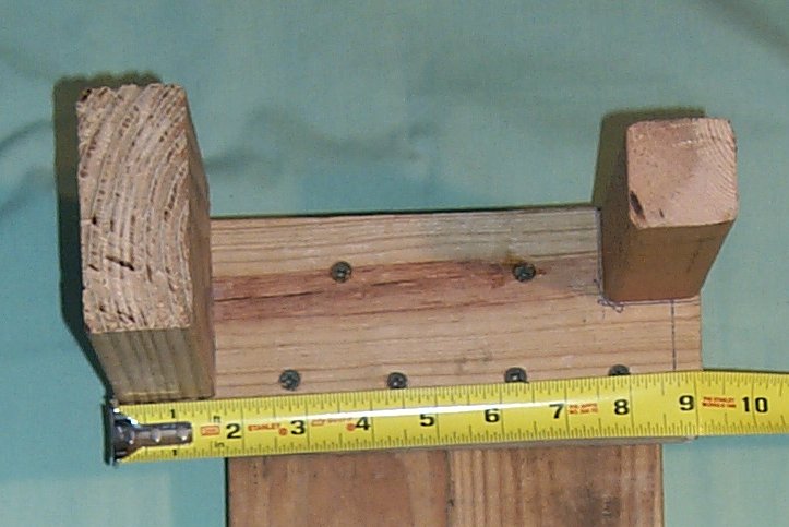
Here is the side view of the adapter. I put the tape measure in front of the adapter to show you that it is the same length as Ross' adapter (20 inches), but the perspective of the camera screwed up the view. The two main pieces are 20 inches long, and are are placed next to one another to create a lift surface 7 inches wide. Note also that the 2" x 4" riser has been offset from the cross piece by one half inch. This puts the riser most nearly centered on the cross member of the motorcycle. I think you could move this out as much as 3/4 of an inch to get it exactly centered... however... my prototype seems to work fine.
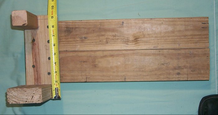
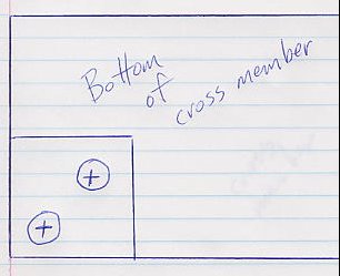
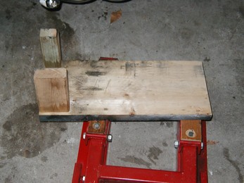
Here is a top view of the adapter. Note that the cross member is 9 inches long. Also note that it is offset to the main pieces. If you have assembled this thing correctly, you will have a two inch overhang on the right side of the adapter (bottom side in the image below), and about a half inch overhang on the left side (top below - the 2" x 2" side)... it doesn't have to be perfect... you can move the adapter around on the engine to line things up. Mainly, you need to make sure the cross member is 9" long. Again, camera perspective screwed up the tape measure measurements.
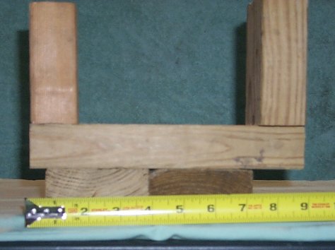
Here is an end view of the adapter. Sorry for the focus... Dewar's can do that to you. You can see that the cross member is offset, 2" on the right, about 1/2" on the left. Thanks to my crappy photographic skills (Dewar's again?), you cannot clearly see the risers... but here are the important measurements. The right riser, the 2" x 4" is 4 and 3/8" tall. The left riser, the 2" x 2" piece is 4" tall. The difference between the two takes into account the kick stand bracket which is located on the left side of the bike.
Sorry for the really crappy photo below... Dewar's in the camera, no doubt. What you are looking at is a 3" long deck screw. I highly recommend that you use deck screws and not nails to put this adapter together. First, you never have to worry about nails pulling loose. True, there are not many lateral forces on this adapter, but a screw guarantees that your creation is never going to loosen up. Second, a 3" deck screw is at least a # 12 size screw... bigger than a nail... very strong. Finally, the deck screws are coated against corrosion... your low tech adapter will remain safe for many years.
Here are the basic assembly instructions. Mount the 2" x 2" piece to the cross member using 2, 3" deck screws. The drawing shows the placement. Next, mount the 2" x 4" piece (remembering the offset of 1/2 inch) using 2 more deck screws. It will help if you drill small pilot holes... no more than about 3/32" to 1/8"... makes it easier to screw in those big ass screws, gets them aligned, and keeps from splitting the wood. The two schematics below give you an idea of where to put the deck screws.
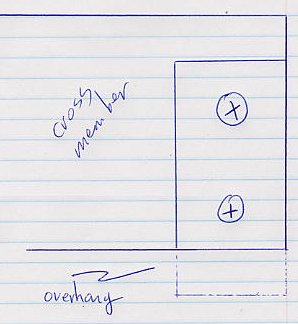
Once you have the risers fastened to the cross member, then connect the cross member to the two main pieces. As you can see from the picture below, six screws were used. I suspect you could use four or eight screws... the lateral forces on this adapter are minimal.
Finally, you need to secure the opposite end of the main pieces... on the underside... this can be accomplished be using a small mending piece as shown in the photo below.
Well, that's pretty much it. Write me at BeastRider
if you want more information.
A Final Note on Using the Adapter
It is MUCH EASIER to get the adapter position under the bike and on top of the lift if you first put a piece of 2 x 4 under the kickstand to make the bike more nearly level.
Some folks have found it difficult to get the adapter positioned under the bike because of very close clearances. I have found that Avon tires are just slightly smaller in diameter than stock Dunlops, and I had to have the SO lift the rear of the bike in order get the adapter underneath. However there are three solutions to this problem.
a) Use a 3/4 or 1 inch piece of plywood for the base... this has been done by other folks.
b) Use a plane and shave the 2 x 4 base... about 1/4 inch does the trick
c) Get two small pieces of 1/2 inch plywood and put them under each
wheel before using the jack and adapter... very easy!
New
I've received a few photos of how other folks have built their low
tech lift adapters. Maybe you'd rather make yours this way.
Again, neither I, nor the persons who sent me the alternate adapter configurations
assume any responsibility for anything that might happen should you wish
to build one of the lift adapters below. This page exists for informational
purposes only.
Other Versions of the Low Tech Lift Adapter
From Chrisj357 (A VRCC poster)
Chrisj357 sent in photos and these directions and comments. His lift adapter is essentially the same thing with a few changes to accomodate his bike.
1. 2 pieces of 2x4 20" screwed together edge to edge (drilling deep
countersunk holes helped)
2. 2x4 crossmember 8 3/4 " long
3. 2x2 crossmember 5 7/8 " long
4. 2x2 post 4"
5. 2x4 post 4 7/16"
6. 2x2 post offset 1 3/8 from back edge (this is edge to center
of post measurement)
Attach it all together with deck screws very securely (angle brackets just for added lateral strenght...still screw up from bottom )
Note: Look at the two cut outs about 3/4 square each for the kickstand micro switch and for the swing arm to swing down. one cut out can be seen in each pic.
One last thing you have to have at least 3/4 of an inch from top of 2x2 post to top edge of 2x2 crossmember for the kick stand mounting bolt to clear........Have Fun!
Placement.....just get the 2x2 post in the little nitch of the kickstand mount and you're all set.
From Mac (Another VRCC poster)
Mac created an even simpler version of the low tech lift adapter. Essentially, Mac dispensed with the horizontal board that runs under the engine case, and placed his adapter directly on the rear lifting surface of the lift. Here is what Mac has to say about his version.
Yes, with the lift under the bike the forward lift arm will pick up the engine at the same time the homemade extension lifts the frame. The shorter side of the brace goes under the kickstand side. You will understand why if you look under there. It seems pretty stable. With the weight of the bike on the forward lift arm the bike seems pretty solid. It would take quite a bump to knock it off.
Here are Mac's submitted pictures.
From Ghost (Abbio) (Another VRCC poster)
And from 1lescarr (Wayne) (Another VRCC poster)
Editor's Note:
Each of these gentlemen used a thinner base board for the lift adapter,
and after thinking about it, this makes real good sense. The lift
is directly under the heaviest part of the bike, and thus there is not
much of a load on the base board. Sure makes it easier to get the
lift under the bike.